04 Jul R&S®ScopeSync; oscilloscopes synchronization feature for MXO Series
Are you working with an application that requires oscilloscope measurements on more than eight channels such as power conversion (three-phase voltage and current, DC link voltage and current as well as sensors), PMICs (multiphase buck converters with 16 or more phases) or FPGAs (complex power up/down sequencing with surrounding system)?

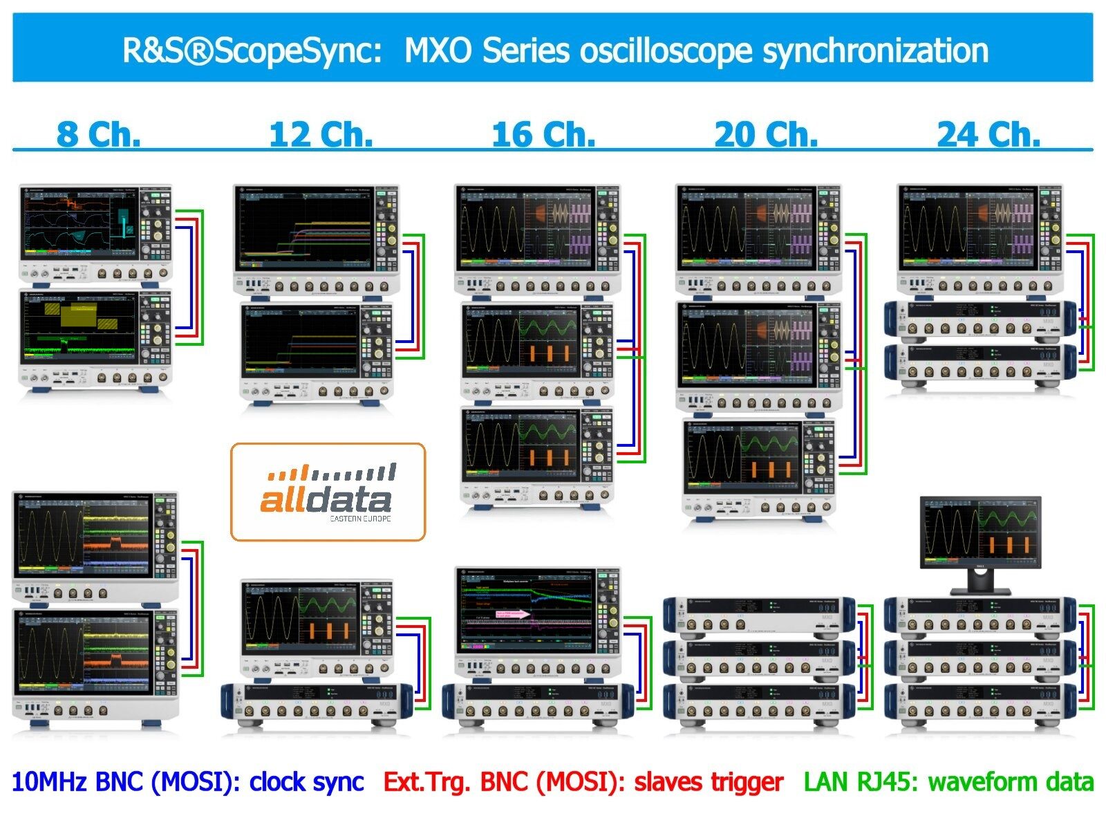
Examples of channel synchronisation in multiple oscilloscopes. Up to 3 oscilloscopes and up to 24 channels.
With the latest firmware release (2.6) Rohde & Schwarz has introduced the ScopeSync feature on MXO series oscilloscopes. The families that support this capability are the MXO 4, the MXO 5 and the MXO 5C.
The newly introduced feature allows to quickly synchronize two or three oscilloscopes for measurements on up to 24 channels. No special equipment is needed, you only need to make three simple physical connections using lan and coaxial cables:
ScopeSync on 2 oscilloscopes

Requirements:
- Scopes clock synchtonisation (MOSI)
- 1 Coaxial cable 50Ω BNC<>BNC
- Scopes trigger synchtonisation (MOSI)
- 1 Coaxial cable 50Ω BNC<>BNC
- Slave waveform transfers
- 1 LAN cable CAT5E
ScopeSync on 3 oscilloscopes

Requirements:
- Scopes clock synchtonisation (MOSI)
- 1 BNC Splitter
- 2 Coaxial cables 50Ω BNC<>BNC
- Scopes trigger synchtonisation (MOSI)
- 1 BNC Splitter
- 2 Coaxial cables 50Ω BNC<>BNC
- Slave waveform transfers
- 1 Network switch
- 3 LAN cables CAT5E
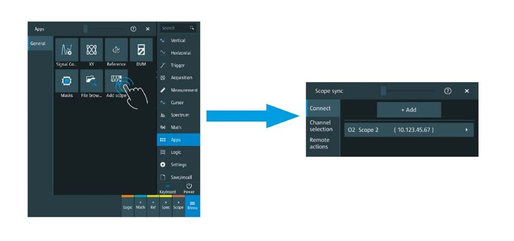
Easily setup directly on the oscilloscope
Using the R&S®ScopeSync menu, enter the IP address of the slave oscilloscopes (referred to as O2 Scope 2 and O3 Scope 3 in the user interface).
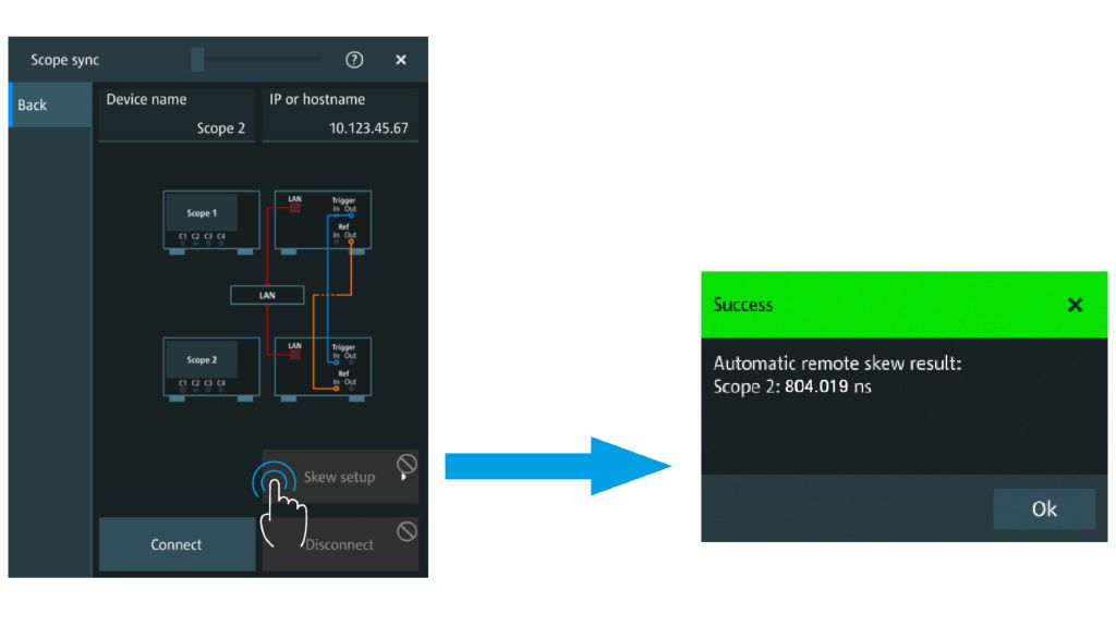
Align trigger with automatic deskew
R&S®ScopeSync automatically aligns all oscilloscopes triggers to the same point in time. An auto-deskew feature measures the trigger out delay between all MXO oscilloscopes and uses this value to align trigger points. Simply connect the passive probes delivered with the oscilloscopes from C1 of all oscilloscopes to the same probe compensation signal and the oscilloscope will make the calculation for you.
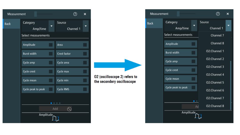
Leverage all your oscilloscope’s analysis capabilities
With all acquired signals in the master oscilloscope, use measurements, math and applications such as protocol decode, choosing any of the oscilloscopes channels as the source.