
19 Oct Unperceived Partial Discharge Causes Failures in Relay Control Circuits
Have you ever experienced abnormal behavior or failures in high-voltage (HV) products for reasons unknown? This case study on HV product testing illustrates the partial discharge (PD) issue that is all too common to HV products, and how to detect it.
 Figure 1 Burnout Example Figure 2 Digital Control Circuit of HV Relay
The above figures show a case where the HV output relay control circuit burned out. In cases of common relay failure, contact problems are relatively well-known, but control IC failures or digital interference are less known. In this example, after ruling out possible poor design of the control circuit and abnormal functioning of the chip, the withstand voltage and insulation resistance of the relay were also judged to be within the normal range. There seemingly were no abnormalities! Analysis of the circuit structure, however, pointed at a suspicious abnormal HV discharge from the relay contact to the control coil.
Generally, the HV relay industry only conducts withstand voltage tests according to specifications, without partial discharge (PD) or flashover tests. However, let us take an actual commercial HV relay with indicated withstand voltage specifications of 14kVdc (which implies a 10kVac peak value) as an example. After testing, it was found that the inception point of general products’ partial discharge was only about 5kVac. According to tests and analysis of HV relays in some markets, the partial discharge inception voltage (PDIV) is only about half of the withstand voltage, which seems to be the common quality issue for this type of HV relay. Most HV relays typically do not have PDIV specifications. If really used in rated high voltage, most relays will produce continuous partial discharge. In this case, the working voltage of the device was designed as max. 5kVac and the relay specification of the withstand voltage between contact and coil was 14kVdc, which suggests no problems with insufficient margins. However, analysis of the relay that caused the problem found that, at 5kVac, there were abnormal partial discharges of hundreds of pC, much higher than measured in normal products.
 Figure 3 General HV Relay PD Volume V.S. Working Voltage Curve
Factors that cause abnormal PD in this type of HV reed relays usually include air gaps or oil marks along the surface of the glass tube, air gaps in the insulation, or conductive impurities that were mixed in. Such deformities cause “partial” withstand problems, making it hard to detect by general DC withstand voltage and insulation resistance tests. Using an AC high-sensitivity PD detector to test products without abnormal PD within the specified voltage is a much more reliable testing strategy.
 Figure 4 Basic Structure of Reed Relay
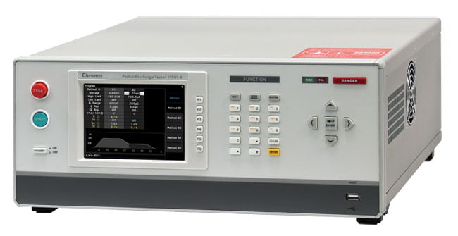
Chroma 19501 series offer built-in AC Hipot testing (10kVac) and PD detection (1pC~2000pC) functions, making it the best solution for abnormal PD detection in high voltage products. Moreover, the abnormality position of this HV relay can be successfully tested by the Chroma 11802-8kV HF HV Tester (10kHz~200kHz) for even faster degradation detection.
Key Features
- Built-in AC hipot test and partial discharge (PD) detection functions
- Programmable AC hipot voltage output 0.1kVac~10kVac
- Up to 0.01μA~300μA high accuracy and high resolution current meter
- 1pC~2000pC partial discharge detection range
- High voltage contact check ( HVCC) function
- Compliant with IEC60747-5-5, VDE0884 and IEC 60270 standards requirements
- Built-in IEC60747-5-5 testing methods
- Separate design for measurement and display unit
- 3 stages of voltage testing function
- PD measured results display (pC)
- PD failure count setting (1~10)
- Traditional Chinese/Simplified Chinese/English multilingual user interface
- USB storage for screen capture
- Graphical editing
- Standard LAN, USB, and RS232 remote control interface
To learn more about this series, please go to the Chroma website through the following link:
Partial Discharge Tester Model 19501-K/19500 Series

